Quantcast
Channel: MF35 FE35 TO35 | Vintage Tractor Engineer
Viewing all 29 articles
Browse latest View live

Video Of Rob’s 23C Engine Running After Rebuild

$
0
0

Rob has kindly sent in this video of his tractor running for the first time after doing a rebuild on the engine.  Here is what Rob had to say.

Hi Steve/Ian

I would just like to say a big thank you for making the 23c rebuild dvd. I went out on tuesday nice warm day bled the fuel system through slackened the injectors turned the engine over till all air was out tightened up the injector pipes and much to my amazement fired up within about 15seconds of cranking all without the aid of the glow plug as i do not have the tractor wired up.   Anyway thanks again i certainly wouldn’t have managed without the DVD.

Unfortunately my stepson did not start videoing till just after it fired up so it was actually running when he started filming and then  i noticed the oil pressure needle was off the scale(top end)lol also the exhaust falling off was quite funny just have to check a couple of the injectors not seating 100%.


MF35, Perkins 3A.152, Strip-Down

$
0
0

The 3 cylinder Engine Rebuild DVD is now available, but Vintage Tractor Engineer thought it would be good to upload a few snap-shots from the project.  These ones are from the engine strip-down and assessment on disc 1.  Photos from disc 2 includes work done at the engineers and the rebuild process.

axle stands in place

Bonnet removed, axle stands in place and ready to start the strip-down.

Cylinder Head

With ancilliaries removed, we soon got down to the cylinder head.

Oil control setting

Note position of the oil supply setting. This one is at the factory setting – aligned with the ‘pip’.

Broken head gasket

Broken head gasket. Has this been caused by overheating?

Removing engine block from tractor

Using engine crane to remove block. Centre of gravity isn’t in middle of the engine, so attach straps/chains to account for this.

Removing clutch from engine

Inserting ‘holding-down bolts’ to facilitate safe removal of clutch.

Engine connecting rods

Looking at piston numbers marked on the connecting rods and caps. Note – they should always be on the same side.

3A.152 crankshaft

using feeler gauges to assess end float on the crankshaft.

big ends and main bearings

Using micrometer to measure big ends and main bearings.

Assessing engine bearings from tractor engine

Even though we can measure components very accurately (and they could well be within specification), we must also make a visual assessment. Just looking at and feeling the bearing surfaces can reveal scratches, scoring, problems and damage.

Bearing shells

Assessing the shells. The white metal has gone and even the copper backing has worn through on the shell at the right hand side. This is when terrible damage can occur and this engine must have been on the verge of seizing.

Pistons, Massey Ferguson 35 engine

Looking at the pistons and rings.

Liner standout

Mesuring liners in relation to surface of the block.

Cyllinder Liners

Cylinder liners, worn smooth and scored/scratched.

worn valves

Looking at the valves.

Worn valve seats.

Valve seats in need of re-cutting.

We always knew from the initial assessment that we’d encounter a particularly worn engine with many problems to rectify.  Basically, after the strip-down, it was clear that pretty much all the usual things were in need of refurbishment or replacement.  This isn’t always the case, as there can be specific issues which need attention whilst the rest of the engine is OK – as long as you know what to look for and understand what components are like when they are in good serviceable condition.

The DVD intends to make it easy for even the most novice of mechanics, so we have tried to show each step of the process in precise detail.  It’s a long process, so that’s how we ended up with the DVD as a 2 disc set!


MF35, 3A.152, Rebuild Photos

$
0
0

We have already shown some snap-shots from the strip-down of this engine.  Today’s photos from the DVD (34 of them!!!) are from the rebuild process, including the visit to the engineers.  Here they are, enjoy…

Valve guides

Pressing out valve guides, most of them were stuck in and collapsed under the press.

Drilling out valve guides.

We ended up drilling the guides to get them out.

Cutting valve seats of MF35 tractor engine

Re-cutting the valve seats to the correct angle. Valve seat inserts needed fitting as there was too much wear on the old seats for a simple re-cutting.

Adjusting the surfacer for the cylinder head.

Adjusting the surfacer for the cylinder head.

Re-surfacing a cylinder head

The surfacing machine working on the cylinder head.

Crankshaft grinding wheel

The crank grinding machine. Here the grinding wheel is dressed to get the correct corner radius for our journals.

Removing crank balance weights.

The balance weights need removing so the grinding wheel can get into the journals.

Grinding a crankshaft

Concentrating on the job! Grinding a crank is a skilled operation, John has done it for a long time and always makes a good job. An interesting process to watch, especially the big ends.

Cutting a step for the new cylinder liners

This machine is about to cut a new step for the cylinder liners to fit onto. The cutter self-centres, in this photo the cutting head is determining its position before it starts to cut.

Fitting cylinder liners

Pressing in the new cast liners.

Fitting main bearings

Lubricate all bearing surfaces as they are fitted together. Use clean engine oil. Note the plastic end fitted to the oil can to prevent the steel oil can from scratching the bearing surface.

Fitting new rings to a piston

New rings being fitted to the pistons.

Aligning timing marks on timing gears

Aligning the marks on the timing gears.

Fitting the bridge

Take some care when fitting the bridge or you will have trouble with sealing the sump and timing cover.

Fitting the cork seals

Fitting the cork seals.

Fitting rope seals

Fitting rope seals. Lots of people get this wrong and end up with oil leaking. Take care and use the correct procedure.

TDC and spill timing marks on the flywheel

Understanding the markings on the flywheel.

Perkins 3 cylinder flywheel

Using a torque wrench to tighten the flywheel bolts.

Adjusting clutch

Using feeler gauge to set the pto clutch on dual clutch tractors.

Clutch fingers

Tool to set the clutch fingers.

Camshaft

Plenty of oil again as the camshaft goes back in.

Timing gears

Injection pump drive gear.

Injection pump

Looking inside the cover plate of the injection pump. The flywheel is at the spill mark before setting this.

Setting fuel injection pump

Rotating the pump to get the setting as accurate as possible.

Fitting engine block

The engine block goes back onto the tractor.

Fitting axles

After fitting the axles and wheels the tractor can then be let down off its stands so it is now safe to work on.

Cylinder head

The cylinder head is assembled and then fitted back to the block. There is a specific sequence for tighteneing down the head bolts.

Setting valve clearances

Setting valve clearances.

Wiring harness

The wiring loom goes back on. Just a few more components to fit and then we will be ready to try and start the engine.

Oil bath air cleaner

Make sure the oil bath air cleaner is cleaned out, fresh oil added and the element is in good condition. We don’t want to ruin all our good work.

Bleeding fuel system

The filters and fuel injection pump have been bled and we can see here the fuel coming out of the injector pipes. These can then be tightened down and we are ready to try starting the engine.

Starting the engine

A few seconds of cranking and away she went. The blue smoke here in this photo will be the excess oil burning off the pistons that we used to lubricate during assembly.

Engine

Engine running sweetly and it’s now time to leave the workshop.

Massey Ferguson 35 Tractor

Off she goes. Good for another 50 years!

I hope these snap-shots from the film go some way to showing the detail we have tried to cover in the DVD – but it is all important detail.  There’s no point in doing an engine rebuild if things aren’t done properly.


Perkins 3A.152 Data And Tightening Torques

$
0
0

There are just a few data specifications which are useful for the 3 cylinder Perkins engine.  These accompany our Rebuild DVD for this engine.


DATA

Tappet Setting (cold) 0.012″ (.305mm)

Operating Oil Pressure 25-30 p.s.i. or more at normal speeds

Relif Valve Setting 50-65 p.s.i.

Backlash in Timing Gears 0.003″ / 0.006″ (0.0762 – 0.1524 mm)

Injector Pressure Setting 120 Atmospheres

Fuel Pump Static Timing 18 degrees B.T.D.C. (or 20 degrees, depending on your engine)

Letter on Fuel Pump Rotor E

Inlet Valve Opens 13 degrees B.T.D.C.

Exhaust Valve Closes 10 degrees A. T.D.C.

Cubic Capacity 152.7 cu. ins. (2.5 litres)

Thermostat Opening Temperature 176 degrees F


TIGHTENING TORQUES

Cylinder Head Nuts 55-60 lbs./ft

Con. Rod Nuts 70-80 lbs./ft

Main Bearing Setscrews 110-120 lbs./ft

Flywheel Setscrews 75 lbs./ft

Balance Weight Setscrews 50-55 lbs./ft

German “Gold Belly” Restored To “as new” Condition

$
0
0

One thing Vintage Tractor Engineer has learnt over the past few years is that tractor enthusiasts in northern Europe are crazy about the gold/grey FE35′s…


Two and a half years ago logistics manager Gunter Birth started the beginning of a busy relationship with a tractor. The machine that chugged now and then through his village was a gold belly Ferguson FE35, built in 1957.   It belonged to an old schoolfriend.

The decades had seen the tractor deteriorate, so it could have ended up on the scrap heap.  Gunter was sad to see the tractor left out in the rain year after year, but its graceful shapes stimulated his imagination to restore its original state.

Today, exactly 1650 hours later, the gold belly is again looking at its best.  The amateur mechanic (with a patient and understanding family!) single handedly dismantled the tractor with the only help from information found on the internet.


Unrestored FE35

Ferguson Diesel Decal


Vintage Tractor Engineer hasn’t seen the ‘FERGUSON DIESEL’ decal on the bonnet before, but there seems no doubt that it is an original part of the tractor.  Gunter couldn’t obtain the decal anywhere, so had them made to the exact same dimensions.  The headlamps were preserved and new wiring fitted.  Many components had to be ordered from suppliers in England, as they were unavailable in Germany.

The tractor is now used on his small plot in North Friesland (on good dry sunny days).  Gunter likes to go to tractor shows and has also used it for straw bale rides at carnivals, which the children have loved.  The tractor gets pride of place in the dry garage (the car has to live in the carport!).


New FE35 sticker

Ferguson Diesel badge

New and old Ferguson Diesel stickers


Gunter used the 23C Engine Rebuild DVD to help with his restoration.

VTE would like to thank Gunter for sharing the photos and videos of his tractor.  We found the bonnet decal particularly interesting.

CAD Drawing, Bracket For Hydraulic Top Cover Removal, MF35

$
0
0

Removing the hydraulic top cover on the MF35 (or any other tractor) is not an easy task, as the cover is quite heavy.  To help facilitate this Vintage Tractor Engineer has drawn a to scale sketch and added phtotos.


bracket


A number of people have used the drawings to manufacture their own bracket which has made the task a true one man operation.

Brian has very kindly provided a more accurate CAD drawing of the bracket, which is in superb detail.  He’s emailed it in to Vintage Tractor Engineer to make it available to everyone.  So here it is.  Just click the link below to download the pdf drawing (557kb)…

Bracket for Hydraulic Top Cover Removal – Massey Ferguson 35

This file may not open automatically in Adobe Reader.  Click the download icon in the top right hand corner of Adobe Reader to bring the file onto your computer screen.


Laser Cut Files

Brian has also sent the DWG / DXF cut files for anyone with access to a laser…

ZIP file of the pdf CAD drawing and the DWG / DXF cut files


Photos Of Dash

$
0
0

Michael has a 1962 MF35, but unfortunately all the plates and badges have been removed from the dashboard at some point in the tractor’s life.  We already have some photos of the decals for various different tractors (a 1962 tractor, MF35 Decals and Badges, Dave’s tractor, Jeff’s tractor, external link to Per’s tractor), but we haven’t ever published photos of the dash.

Our own 35 is also a 1962 tractor, so here are the photos of our dash…

Massey Ferguson 35 Dashboard photo

The plate on the left hand side is the starting instructions. The plate on the right hand side is the serial number plate.


MF35 dashboard photo

Positioning of the Diff Lock decal.


MF35 decal or sticker

Text from the Differential Lock decal.

The Starting Instructions plate on our tractor is half rubbed away, so the text is illegible.  The tractor did all the loader work on the farm for over 30 years (until we purchased a telescopic handler in the early 90′s), so I think when the clutch pedal was depressed we all had a tendency to hold our knee against the dash to help hold the clutch down.

The serial number plate on the right had side has the following text on it…


MADE IN ENGLAND BY

MASSEY FERGUSON

TRACTORS LTD

COVENTRY, ENGLAND

UNDER ONE OF MORE OF

THE FOLLOWING PATENTS

list of 16 patent numbers

FOREIGN PATENTS

OTHER PATENTS PENDING

FE-35

the tractor serial number


The plate is exactly as the one on Per’s website, other than Per’s plate only has 15 patent numbers listed.  The 16th patent number on our plate is 888230 (positioned in the third column, below 305065).

Clutch Squeal

$
0
0

Tom has recently refurbished the engine on his 3 cylinder MF35.  However, after replacing the clutch assembly with a new one he has experienced a squeal.  This is what Tom said…
‘ The clutch is producing a quiet but definite squeal when the clutch pedal is depressed. I set the two-stage pto adjuster nuts as per the manual/DVD  and the pto engages correctly and stops as it should when the clutch is depressed. I can select all gears and the clutch does not slip- the tractor drives and stops perfectly. I installed new pilot and clutch release bearings as part of the clutch replacement and set the pedal freeplay as per the book. Despite this I can hear a squealing as soon as any weight is transferred onto the clutch pedal, the tone of the squeal changes slightly but does not stop as the pedal is pushed further down. I wonder if you have experienced anything like this with a new clutch replacement on these tractors and if so any light you can shed will be most gratefully recieved. I realise that splitting the tractor is probably the answer and this is not a problem but I thought you might have some pointers on what to look out for. Many thanks again for a very informative and easy to follow DVD’.


VTE’s First Thoughts

Firstly, you say that the noise starts as soon as you start to transfer any weight on the clutch pedal.  This discounts any problem with the pilot bearing as anything wrong with this bearing would only become apparent when the clutch pedal is depressed fully to the bottom. I strongly suspect that the problem is either a faulty clutch release bearing or that the dowels are not there which locate between the engine back plate and the clutch housing.  The bolts that hold the tractor together at his juncture are in fact smaller than the holes they locate through, as a result if the dowels are not present then the clutch fingers can become non-concentric with the release bearing (i.e. it is the dowels that hold the clutch concentric to the engine shaft). This situation can wear the ends of the fingers off in no time at all as the fingers shuffle on the release bearing.

I would advise not to use the tractor until you have taken a look at it (in fact it could be too late and the ends of the fingers could already have worn off, we’ve seen it happen before).


Clutch fingers

Setting clutch finger height


Tom’s Update

‘Update on the 35 clutch with good and bad news I suppose. I can find no obvious problems with the clutch and thrust bearing set-up. The release bearing looks to be contacting the toggle set screws equally and having replaced the bearing the squeak is still audible, however I believe I originally thought that the squeak was present throughout the pedal travel but it definitely disappears when the clutch is down to the second stage ie. pedal right down.

Is it possible that this noise is just the new surfaces contacting and may be eliminated when the tractor has had some use? I should say that I did not adjust the release toggle set screws on the new clutch assembly as they are marked with paint and I was assured that they come factory set just leaving the pto adjusters to be checked/set. I don’t think that should make any difference for this particular symtom but I may be wrong.  Any more thoughts  or advise is much appreciated and gratefully recieved.  Just for information, the new clutch assembly is a Vapormatic part.’


Other Things Which Could Be Causing The Squeal

Well the clutch shouldn’t be excessively noisey.

As you say, the pto adjusters should be set correctly, but you can check them.  88-92 thou is the spec, but they should all be as close as they can to each other.

Just a few more thoughts.  Could it be a squeek between the two input shafts?  So what I mean is when clutch is depressed to first stage the gearbox input shaft will stop rotating but the pto shaft will still rotate.  But when you depress the clutch to the bottom (end of second stage) then the pto input shaft will also stop rotating.

Is there any chance the clutch assembly has been built up incorrectly at the factory?  pto plates in wrong way round?  Are the metal segments that go between the clutch cover and the flywheel in place, not been removed by a previous owner?


Can Anyone Else Offer A Suggestion?

Tom adds ‘The noise certainly ceases at the second stage its just the initial couple of inches after pedal free play that produce the high pitch squeal.  The noise may not be perceptible to the ordinary user of the machine I don’t think, but as you know when you play around with these older machines, taking them apart and putting them back together, you tend to look/listen for problems as second nature.

Has anyone else experienced the same symptoms and got to the bottom of the problem?  Just leave a comment below or Contact Us if you’ve got any ideas for Tom.


23C Air Cleaner Oil Level

$
0
0

We sometimes like to re-visit previous topics.  This is a discussion from the forum about the oil bath air cleaner oil level.  VTE has a few bits of information to add at the end of this article…


jbo1948

I have never been very clear as to how much oil should be put in the oil container at the bottom of the filter assembly for a 23c engine. Within the oil container there is a ring (I think called the deflector ring) which has some holes in it – should there be any oil within this ring or should the oil be kept outside the ring up to the level of the holes? Apologies for such a basic question but any guidance would be much appreciated.

Regards

  • mr.happy19690

    i think there is a line stamped into the bowl itself. i have learned that if you put too much oil in the engine will suck it out and burn it up. it makes for quite a smokeshow.

  • mr.happy19690

    upon looking in my massey bible there IS a mark in the wall of the container cup.

  • jbo1948

    Thanks for your response. The mark to which you refer, is it on the outside of the bowl or inside? I am not sure about the internal ring i.e. should the oil be kept between the outer wall of the bowl and the ring with no oil within the ring?

    Regards

  • baldeagle60

    I am sorry, have not got a clear answer to your question. I am looking forward to finding out the same….
    Just wanted to point out a recent problem I have had with air cleaner. During a recent freeze up, the tractor started and smoked like crazy, and did not have any power at all. I could not get the throttle to work. checked the diesel, then took off the air cleaner. I had just cleaned it a couple weeks ago . It was full of clear Ice, and blocking the air intake. (ME THINKS SOMEONE TRYING TO SABOTOGE THE TRACTOR?)I do not know where the Ice came from as it is sealed up to keep the rain out.
    anyhow after removing the clear ice, and again cleaning it out and replacing oil in ring. it ran like a wonderful 35 should…. Looking forward to you getting a reply about actual whether or not you put oil in inner ring….

  • Fergie Man

    Hi Baldeagle 60 …the easiest way to avoid any confusion is to fill the centre ring as you describe it up to the holes…..the oil then will run out of the holes and start to fill up the outer ring. When the outer ring and inner ring are both at the same level you have cracked it….if there isn#t any visible level mark inside your air filter bowl you can then make your own mark where the oil level settles….this should help you for future reference…..Geoff

  • mr.happy19690

    since you were asking i decided to check mine and found that i thought it was low. i added some and ran it at idle no problems then we got some snow. and i went to clear the snow. the tractor started smoking horribly and then the engine raced the throttle did nothing so i pulled the kill knob the engine continued raceing. horrified i put the tractor in gear and held the break. to stall it. after some carfull observations i figured out that the engine was sucking the oil out of the air filter and then combusting it as fuel in the engine hence why the throttle and kill didnt work. very strange. any way i guess i overfilled mine.
    the service manuel is very vage about it it just says that theres a line. i filled mine to what i thought was the line. so i think id listen to geoff

  • baldeagle60

    the bottom line on the air cleaner (on mine anyhow) says fill to here. this is the level which the oil will go up to which is level with the holes between the inner ring and the outer ring. I have found this discussion helpful, as it confirms what I have been told by others, and also the tractor expert at my tractor engineers. hope this is a help. Dennis

    http://i32.photobucket.com/albums/d40/American_hedgehog2/tractor/aircleaner1.jpg

    Photobucket


    VTE says…

    The air intake into the cleaner is at high velocity down a vertical tube, the bottom of which is submersed in the oil reservoir.  The concept is that dirt particles will continue downwards into the oil bath due to centrifugal force (the air suddenly changing direction back upwards)  The now upwards travelling air carries with it some oil and remaining dirt particles into the mesh element.  The oil and dirt are caught in the element and then drip back down into the reservoir (oil carrying the dirt particles).

    In very cold weather it may be necessary to blend up to 25 percent paraffin with the oil so that the oil can flow freely.

    The oil level can rise in the reservoir due to the addition of captured dirt particles.  The oil level should not be let to increase any more than 9.5mm above the level mark.  In very dusty conditions this may need to be checked more than once per day.

23C Fuel Injection Pump, Aligning The Circlip

$
0
0

The Question

We’ve had a query about aligning the letter G against the circlip mark when timing the fuel injection pump on the 23C engine.  Bob has followed the 23C Engine Rebuild DVD and notes that on the DVD it shows the circlip mark on the lower side of the clip gap.  However, Bob’s tractor has the circlip mark on the hole above the circlip gap.

Why is this?  Which one is correct?

23C Fuel Injection Pump

‘G’ mark on pump aligned to mark on circlip (photo as per DVD)


The Answer

To a diesel engineer, when aligning the timing circlip with the timing groove the orientation of the criclip isn’t important.  What is important is that the pump is timed and set to the groove on the circlip.

So your pump may have been overhauled and the diesel engineer has set the pump to the groove (i.e. the circlip may have been turned).  So  just re-set it to how it currently is.

Further to that, some DPA pumps use circlips with no grooves, in which case the squared end of the circlip is the timing indicator.  If in doubt have it checked at a diesel engineers if you have a problem.


How Is This Setting Made?

There were several different versions of the pump fitted to this engine and each version has a different test plan to set up the pump.

The diesel engineer will remove an injector and connect an injector tester to that line (which injector line it is will be specified in the test plan for that version of the pump), rotate the pump to a certain position, apply pressure to the system using the injector testing machine and testing fluid, rotate the pump in the specified direction until it goes solid, maintaining the pressure he will then move the circlip to be in line with the scribe mark.

Tractor Link Arms Will Not Lower

$
0
0

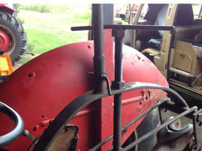
Your link arms will not lower.  It’s a frustrating problem.

We commonly associate hydraulic problems with poor pump performance and reduced or slow lift capacity.  However, we get quite a number of people reporting that their link arms won’t lower.

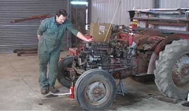
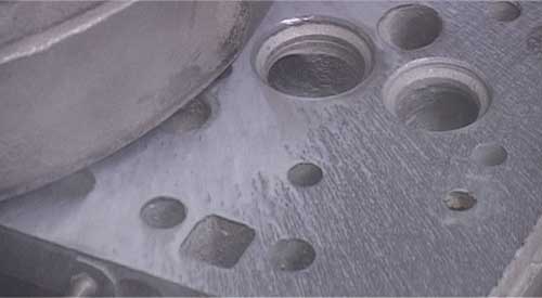
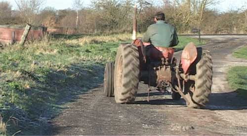
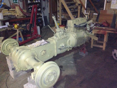
We’ve had an email from the owner of a Massey Ferguson 35 who has this problem, so we’re going to take a look at what could be the problem and what needs to be done to get the system working again.
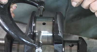
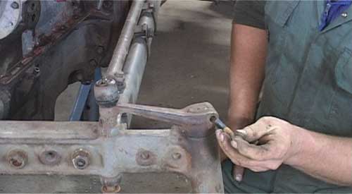
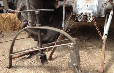
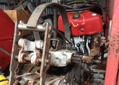
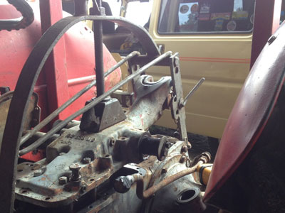
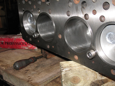
Lift Arm Shaft

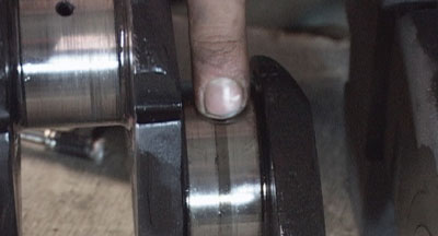
The rate of drop of the arms should be set so that the lower links will just fall under their own weight when lifted by hand.  This is altered by adjusting the cap screws in the ends of the lift arms shaft.

If the screws are tightened too much, not only will it prevent the arms from lowering but it can also cause erratic action of the hydraulic system.

However, if a heavy implement is attached to the linkage and the arms will still not drop then it is likely to be related to the pump control valve.  We first need to uderstand how the position of the control valve raises and lowers the arms.

The Pump And Control Valve

The lower part of the pump is immersed in hydraulic fluid.  When the control valve is open it allows fluid to be sucked up into the pump and then on into the discharge passage (to pressurise the lift cylinder and lift the linkage arms).
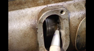
MF35 control valve

The control valve

The contol valve slides to regulate the supply of fluid to and from the lift cylinder, the degree of which depends upon the relative settings of the manual control levers (and also by any control exerted automatically by the hydrauilc control mechanism).

The sliding control valve is essentially seperated into two compartments, one facilitating fluid inlet to the pump and the other compartment allowing an outlet from the high pressure chamber.

NOTE, the control valve is always held towards the drop position by a compression spring.

  • When the valve slides forward, its inlet slot passes within the suction chamber, hence the pump can draw fluid and pressurise the fluid into the lift cylinder.
  • When the valve is positioned centrally, both the inlet and outlet slots are positioned outisde of their chambers and hence the oil is locked in the system and the linkage arms remain stationary.
  • When the valve slides rearwards (by the force of the compression spring) the outlet slots are brought within the discharge chamber, thereby permitting oil to drain from the system (lift cylinder) back into the sump.

The rate at which oil drains from the system depends on how much of the outlet slot is moved into the discharge chamber.  In fact there are two pairs of slots in the discharge end of the control valve.  The second pair of slots are positioned further along the control valve, so if the control valve is moved further rearwards then all four slots discharge oil and thus the rate of drop of the lift arms increases.  The second pair of slots are also larger.
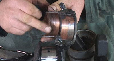
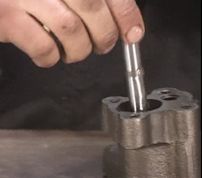
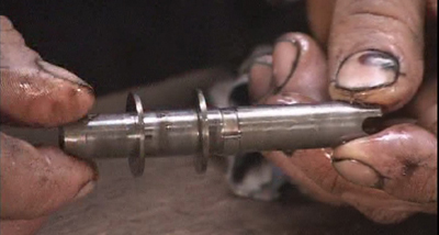
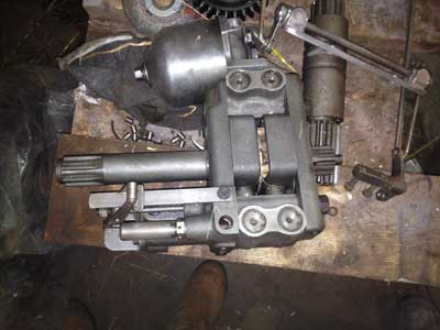
Close up of control valve

Inlet slots at the rear end of the vavle (LHS of photo), small outlet slots at front end of the valve (RHS of photo).
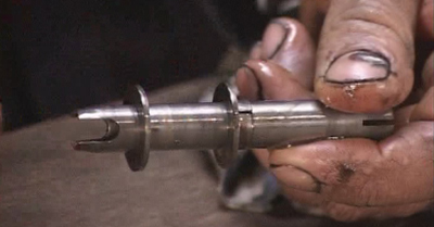
MF35 control valve

Control valve rotated 90 degrees to previous photo. Now we can see the second pair of larger outlet slots (RHS of photo).


What Can Go Wrong?

General Information

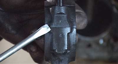
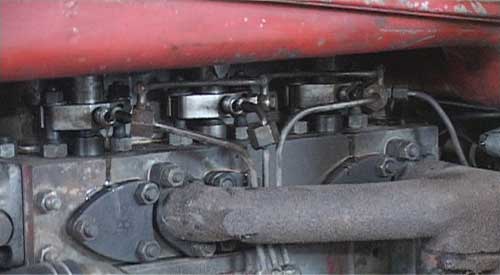
The control valve needs to be oil-tight to the bore of its sealing washers (the washers seperate the suction and discharge chambers).  The fit between the washers and the control valve is therefore extremely precision as it must seal under pressure but also facilitate the control valve to move.

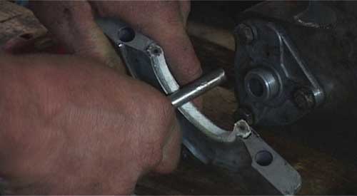
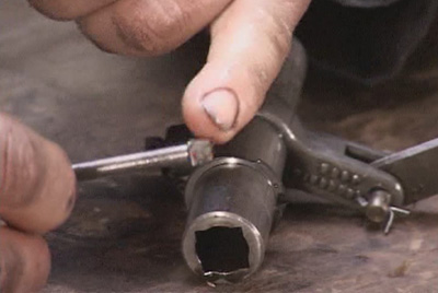
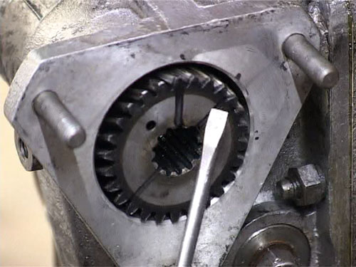
To prevent the control valve from sticking there is an oscillating mechanism.  The oscillator is driven from one of the pump eccentrics as the drive shaft rotates.  It is not uncommon for the square end of the oscillator push rod to be rounded off.  This would cause the oscillator to be inoperative and so the rod would need to be replaced.

MF35 oscillator

Square end of the oscillator push rod

The exteme accuracy of fit between the control valve and its sealing washers means that any small particle of dirt could cause the valve to jam.  Extreme care should therefore be taken with cleanliness of the system.

  • Cleanliness of the fittings should be considered when connecting to the hydraulic ports (eg. connecting a tipping trailer or front loader).
  • Change transmission fluid every 750 hours (or annually).  Clean the pump filter (if fitted) and remove any deposits on the magnetic transmission casing drain plug.
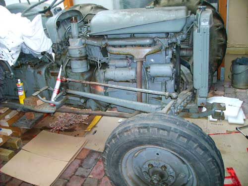
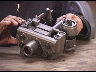
MF35 hydraulic pump

The hydraulic pump with strainer filter

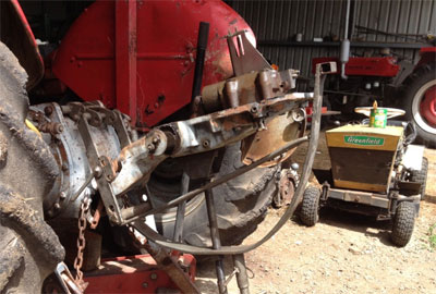
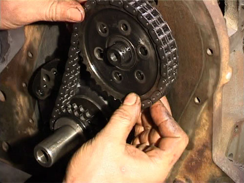
Compression Spring And Control Linkage

Failure of the compression spring would mean that the control valve will not be pushed rearwards into the ‘drop’ position.  Failure of the compression spring is quite common.
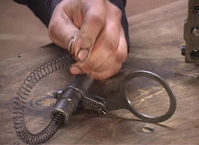
MF35 hydraulic pump oscillator spring

The oscillator spring, although not a very strong spring, is quite long. It is possible to hold the spring pressure by hand whilst removing the retaining circlip.

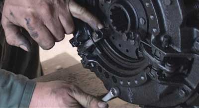
Also, it is possible that a failure/problem/jamming of the internal control linkages would prevent the control valve to move rearwords into the ‘drop’ position.

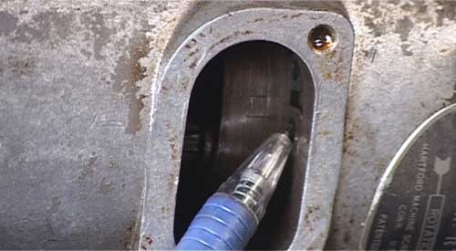
Isolating The Problem

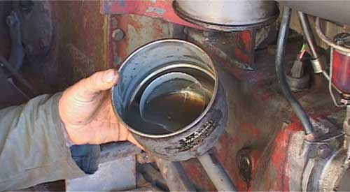
It is possible to drain some of the hydraulic fluid and remove the right hand transmission casing inspection cover to take a look inside the tractor.  Do not put your hands through the inspection hole if the engine is running.  It should be possible to see if the levers are moving the control valve and to see if the spring is returning the control valve to the rearwards (drop) position.

Removing the stand pipe would also isolate the pump, control valve and control linkage mechanism as the problem.  i.e. if the stand pipe is removed then the problem is either associated with the lift cylinder itself or the lift arms binding.  Beware, even with the engine stopped,  the hydraulic fluid in the stand pipe could be pressurised.

It is possible that the lift cylinder seizes in the ‘up’ position if the tractor has not been run for some time, rusting in place due to excess moisture in the oil and the transmission casing.  An example of this occuring is given in the comments section of this page.
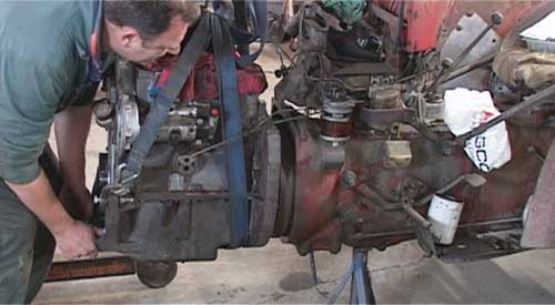
Making The Repair

Obviously the necessary repair depends on what you suspect the problem to be.

Earlier in the article we looked at what to do to set the lift arms to prevent them from binding.

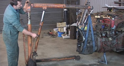
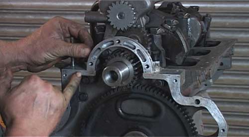
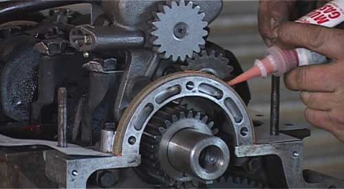
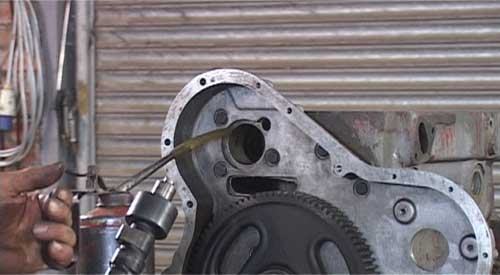
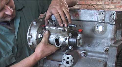
Repair of the control valve and its oscillating mechanism will require removal of the hydraulic top cover to access and strip the pump components.  This is an involved process and you may find the MF35 Hydraulics Troubleshooting And Repair DVD helpful to guide you through this process.

MF35 hydraulic pump

Pump inside transmission casing (top cover removed)

This article was based around the Massey Ferguson 35 tractor.  The information will also be useful for many other models that have a similar control valve and hydraulic system.


Improved Bracket – Hydraulic Top Cover Removal

$
0
0

Here at VTE we already have a simple bracket design for helping to remove the hydraulic top cover for the MF35 (the same principle would apply for many other models as well).

The top cover is a heavy component and the bracket is designed so that the cover can be removed and inverted for servicing by one person.  However, because this design of bracket uses a simple hinge action it isn’t particularly easy to remove the top cover without slightly catching the delicate levers against the transmission housing.

More Sophisticated Design

Dave has sent us some photos from his place in New South Wales, Australia, of his more complex bracket that he has designed.  Dave’s bracket differs in that it facliitates an initial straight and gentle lift of the top cover, before the bracket is then flipped over for servicing.

Here are the photographs of the design (many thanks Dave!) …


Hydraulic cover removing bracket


MF35 hydraulic servicing


Tractor hydraulic servicing tool


Massey Ferguson service tool


tractor hydraulic repair tool

Ferguson FE35 Restoration

$
0
0

Philip has kindly sent in some photos and video of his Ferguson FE35 Goldbelly restoration.

The tractor was originally purchased new by his father in 1957 and like many dissused tractors was abandoned under a hedgerow for about 20 years.  Philip rescued it and has recently been undertaking a full strip-down and restoration.

The first photo shows the tractor in a pretty awful state.  But then we see a transformation and some video (at end of article) of the completed tractor working in the polyhouse.  Philip says the engine sounds just as he remembered it, really sweet and smooth.

Subscribers may need to visit the website to see the videos if viewing this in your email.

The tractor was in dreadful condition before the work began, having spent so much time abandoned outside.


Ferguson FE35 tractor, unrestored


But then came a lot of hard work, dedication and many hours in the workshop…


Ferguson FE35 Gearbox


FE35 engine being rebuilt


Rebuild FE35 tractor engine


MF35 or FE35 hydraulic pump, Ferguson tractor


Grey gold Ferguson during restoration


Fuel tank for FE35 tractor


FE35 chassis castings with undercoat paint


Gold paint applied to tractor


Paitwork of tractor nearing completion


FE35 gold and grey tractor


High quality tractor restoration

The smile says it all


The completed tractor

My turn to have a go!


Restored Ferguson back home to do some work

Delivered back home


Completing a quality and full restoration like this is huge task, but is one of the most satisfying feelings to see such a quality rebuild.  Well done to Philip and we hope the tractor gives him many more years of faithful service.

Many thanks to Philip for sending in these photos and videos for us all to enjoy.

The first video shows the frist starting of the engine.  Initially there was a faulty injector, but this was repaired and then the engine started up and ran really well.

The second video shows the tractor back at work in Philip’s polyhouse.  Good for another 50 years!


Ferguson FE35 Glow Plug Information

$
0
0

Many Standard 23C diesel engines have the ‘Thermostart’ heating and vaporising coil fitted in the inlet manifold.  Effective as this is, FE-35 tractors sold for use in areas of the world where extreme cold temperatures are expected were often fitted with ‘cold climate heads’ that have individual heater plugs for each pre-combustion chamber.  Tractors equiped with this system do not have the thermostart system fitted.


Heater plugs fitted to massey ferguson 35 4 cylinder head to aid starting


It is still possible to get the glow plugs (or alternatives) from some suppliers, but they are becoming more difficult to source in some contries.  We are going to take a look at the system, the components, the wiring diagrams and an alternative system built from more easily obtainable components that offers some advantages to the original system.

We’ve got some really helpful photos and diagrams to show you exactly what to do if you need to work on the heater system.

——————————————————————————————————

Per owns a cold climate FE-35 over in Canada, and he’s written a comprehensive article about the system on his tractor and how he has converted it.  The following information summarises Per’s article, but to read the full article then we would recommend taking a look at Per’s page on the subject (and there’s lots more great stuff on his website too!).

If you are able to source the original type of glow plug and ballast resistor (or manufacture one) then you would have no need to change, but this information may be useful for those of you who cannot source the original equipment.


The Glow Plugs

The heater plugs as specified in the MF manual are…

KLG. Z 161/3  (1.7V. 38 amps)

superseded by…

Lodge D.T. 14 L-1.7V  (1.7V. 38 amps)

KLG. GF. 205.T  (1.7V. 38 amps)

The two plugs on the left and centre of the picture below are what was removed from Per’s tractor.  The plug in the right of the picture is the new replacement plug that also fits these engines (and comes from a Land Rover engine).  However, the new plugs are 12V, so it would be necessary to convert to a parallel wiring system if you use to this type of plug.

The old plugs are easily identifiable by the insulating washer (even when fitted to the engine).


The Originals, And Replacement Plug

glowplugs for Standard 23C diesel engine

Original Wiring Diagram

Wiring diagram for glow plugs


New Wiring Diagram

Alternative wiring diagram for MF35


Wiring the new glow plugs in parallel also gives us an advantage.  Using the old series wiring system means that if one plug fails, then none of the others would work either.  Parallel wiring means that if one plug were to fail then the other three would still be receiving current and hence working.

The other train of thought on this is that if a plug blows when in series you will know something has gone wrong and you will replace the faulty plug (there is a warning lamp on the original system to indicate this – if it doesn’t light).  The potential disadvantage of parallel wiring is that you don’t realise when one plug blows, then some time later the next plug may blow.  The operator may then think that starting performance is slowly deteriorating and may not realise it is the plugs.

It is also possible when the corkscrew / coil type of glow plugs burn out, that the element can drop into the pre combustion chamber and get into the cylinder itself.  The probe type of plugs are much less likely to suffer from bits falling off.

The Ballast Resistor


Ballast resistor for MF35 heater plug circuit

Newly manufactured ballast resistor.

The ballast resistor was originally fitted to prevent over-loading during the initial heating period.

The ballast resistor is not necessary with the new plugs wired in parallel, as each plug is 12 volts.

The ballast resistor in the photograph above was manufactured for Per by one of his friends.  His friend used 14 gauge Nichrome wire and made four new fibre washer insulators.


FE-35 Glow Plugs

$
0
0

We recently wrote about Ferguson FE-35 glow plugs.  The vital piece of information in the article was that glow plugs from a Land Rover engine also fitted the Standard 23C engine.  Land Rover parts are quite easily obtainable, so this is a good source of supply if you need glow plugs.

We have been given some information as to why this may be, in a historical context.

In 1954, the Rover Motor Company was in talks with Standard-Triumph with the possibliity of a merger.  Standard manufactured the 20C engine as fitted to the Ferguson TEF-20 tractor (also fitted to the Standard Vanguard).  The merger never actually went ahead, but during talks the Rover engineers were able to study the designs of the Standard diesel engines.  This helped give them the knowledge to develop their own diesel engines for the Land Rover.

The final design of the 2.0 litre Land Rover diesel engine (unsurprisingly) had some similarities to the Standard engine, including the use of Ricardo Comet swirl chambers with heater plugs fitted as an aid to starting performance.  Hence (Vintage Tractor Engineer believes) the heater plug fittings are exactly the same in the Land Rover engine (1957-1962) as they are in the Standard.

The Take Away

The Land Rover glow plugs will fit the Standard 23C engine with cold climate head.  The Land Rover plugs are 12V, so they would need to be wired in parallel (originally the glow plugs were wired in series on the 23C).  See the FE-35 Heater Plugs page for wiring diagrams.


MF35, 3 Cylinder, Loosing Oil Pressure

$
0
0

We’ve had this question come in…

After about 1 to 2 hours running my MF35 3 cyl 1960 model starts loosing oil pressure.  Also if taking out the oil dipstick, exhaust gases/smoke is coming out.  How can I fix this? can a good DIY man fix it without an engineer? Is it safe to continue running the tractor in this condition if topping up oil when necessary? The tractor is really running well and always starts first go, even in the coldest of winter months. L.H., United Kingdom


These Are Classic Worn Engine Symptoms

There are a couple of things going on here.

The cause of the drop in oil pressure is likely to be either a worn oil pump, worn crank shaft bearings/the crank itself, or likely a combination of the two things.  As the engine gets hot the oil becomes less viscous (thinner) and so passes past the worn bearings more easily (more quickly than it should do), and then the pump (which may also be worn) cannot keep up with the demand – hence you get a drop in oil pressure.

Here’s an example of some very worn bearings…


Bearing shells


We need to measure them against published figures.  Remember to measure them across the different planes, as they are usually more worn where they have taken the force of the piston/combustion.


big ends and main bearings

Using micrometer to measure big ends and main bearings.


If you are getting exhaust gasses coming out of the oil dipstick then that is a certain sign that the cylinder bores and the pistons/rings are worn.  This lets exhaust gasses down into the crankcase, into the sump and the escape route is through the dipstick.


Cyllinder Liners

Cylinder liners, worn smooth and scored/scratched with a step where the piston has travelled to.


The danger when they get really bad is that if the crankshaft bearings or big end bearings get worn through too much then they can weld and seize the engine.

Basically the engine is ready for a full rebuild.  It is quite surprising that it is still starting on cold days, as the lack of compression when engines get this worn usually effects starting performance.

Can you do it yourself?  You can do much of the work yourself.  All the dismantling and rebuilding work you can do yourself.  This is quite time consuming, so you can save a lot of money here.  It depends exactly what is wrong if you will need an engineer or not.

It is likely that you will need some jobs doing by an engineer.  The photo below is from a four cylinder tractor, but it shows what cylinder liners should be like!!


Skimmed engine block with new liners fitted

Skimmed block with new liners fitted. Note the cross hatch hone marks clearly visible.


The cylinder liners will need to be pressed out and new ones pressed in and the block may need machining to get the correct height and fit of the liners.  The valves and guides is also a job for an engineer to get the best job done.  The crank may also need either polishing or grinding, which is a specialist job.

Our MF35 Engine Rebuild DVD would be of use to you to assess your engine and also useful for you to see how to do all the work, including setting the tappets and the timing etc.

The symptoms of this engine really are classic characteristics of a generally worn engine.

3A 152 Injector Nozzle Pressure Setting

$
0
0

Information on setting the injector nozzle pressure settings for a Perkins 3A.152 3 cylinder engine as fitted to a Massey Ferguson 35 tractor.  This discussion follows the story of Ryan’s tractor.

When trying to get good starting performance there may be more than one issue that needs attention.  Ryan began by reconditioning the injectors, but also had to undertake a little maintenance on the starter motor…


  1. Ryan Jackson

    Hi all,

    I’m struggling at the moment, I’ve just reconditioned the engine on my MF 35 and while as was at it I tested the Injectors too see what the spray pattern, yes it was terrible – dripping out – not spraying.

    Therefore there was no choice to exchange the Tips – the question is what pressure should I set the Nozzle tips to break off at?

    I’ve heard they should be 2060 psi = 142 Bar and somebody else said they should be 185 Bar.

    I don’t know were to be at! And I don’t want to set them at a wrong pressure and fit them – and then they will wash the liners etc.. After investing many hours reconditioning the Engine.

    Guys do you know what pressure I should set them at? your help would be very much appreciated.

    Ryan Jackson

  2. Ryan Jackson

    Hi Guys,

    I did some rooting today. I reckon I’ve got the right setting now 2500 PSI = 174 Bar. Anyway I’m going to set them to this.

    Just want to keep you men up to date – in case anybody else needs this values.

    Hopefully we will get some smoke this weekend – here’s hoping!

    J

  3. admin

    Hi Ryan,

    For the 3 cylinder Perkins it is 120 atmospheres (about 121.6 bar).

    For the 4 cylinder Standard engine is it 130 atmospheres (about 131.7 bar).

    Have you done your own injectors? What process and equipment have you used to do this? I’m sure everyone would be very interested to learn the technique if you have a moment to teach us.

    Regards,

    Steve.

  4. Ryan Jackson

    Morning Steve,

    Thanks for the feedback. Shxt I have set the injectors to 174 bar. No worries I can adjust them again. Steve it seems a little too low on the pressure. But if you say so.

    Yeah did not get any smoke yet.

    Last night I was turning the motor over to check if I was getting oil pressure / delivery to the rocker shaft.
    Got the oil up there, so that is good. But I did notice it was very hard to turn over even with the injectors out.
    When I re-worked the engine the crankshaft was turning over freely. But that problem you always get on those motors- the rear main brg oil seal “rope seal” is always leaking. So when i fitted the new one I made sure it was tight on the crankshaft – this made the engine hard to turn over – but I never thought it would be so hard with the starter on it. She is tight. You could cook eggs on the starter motor after turning over. And I had a big ass 135 AH Forager battery on there.

    Tonight I will check the starter to see if it is “Lazy” measuring the voltage drop when turning over and will clean the brushes too. In the worst case, we will just have to tow her to get her started and bed that rope seal in. I think the voltage should not drop below 10V when cranking from the power supply into the Starter motor and the ground/earth.

    What I did with the Injectors, got a replacement set of Nozzles – as that is the only thing which “Normally” goes wrong “they drip, spray unevenly etc.”. So you just have to fit the Nozzles and then simply adjust the the tensioning spring holding the needle down. How you set them is by using a injector test gauge see link – http://www.bosch.co.za/content/language1/html/3315.htm

    You do not need to send them away to be reconditioned – if you have the tools handy you can DIY it.

    Thanks for the info Steve

    BR
    Ryan

  5. Ian@vte

    Hi Ryan
    Re injector pressures.The info in my factory manual concures with Steves figures,however it has been said that a small increase to the pressure for the 23c engine does help with starting.Add approx 10 to 15 atmos.??Ian

  6. Ryan Jackson

    Well men,

    Thats me loving life now!

    We got smoke tonight – Beautiful!

    The rat was not the back-end seal. It was the starter motor, I turned the coil down where the brushes run on and squared the brushes up too. The power is coming on there good and strong. When I was setting the solenoid fork up, I did notice the IMPORTANCE of setting is right. Just a little turn too far and the pinion gear rides into the housing and the motor turn slower. After a little “screwing” about we got her sweet. Riding to the end “housing” but no slowing the rotation speed down.

    After modifying the fuel in-line to run out of a 5L (in stead of the normal tank) and then and blead her. First turn of the key or better to say BiG screwdriver to bridge the starter she brust into life.

    It was a long time coming but was sweet, until I smoked the workshop out. That is a great training excersie for the Fire Department – Blue smoke and eye lids for Chinaman on me – but it was worth it.

    So we are away with a mixer now.

    Just back to pressures on the Nozzles – I set them to 130 Bar. Even though our Steve and WSM says it should be 120Bar. I did notice at 120Bar the nozzles did not spray as nice as at 170+Bar. The question was – what can the Fuel pump deliver too – pressure. So she got the 130Bar set on the injectors – until yet no problems incruded. Fingers crossed!

    be good

    Jackson


23C Engine, Fitting Injection Pump Timing Gear

$
0
0

The injection pump timing gear must be fitted correctly in order that the injection pump timing is correct for the Standard 23C engine.

The process of how to do this is shown in our MF35 (23C) Engine Rebuild DVD.

One thing to be aware of is that the measurement (45 degrees anti-clockwise from the master spline) is not definitive, but approximate.  Another difficulty here is that the gear rotates as it slides in and meshes with the intermediate gear.  It is the fully meshed poistion of the gear when the 45 degree line should be close to vertical.


injection pump timing gear


After fitting the injection pump it may be found that the ‘G’ mark will not line up with the circlip as it should.  If this is the case it would then be necessary to rotate the injection pump timing gear by one tooth (in either direction) and refit.

MF35 Draft Control Spring Nut

$
0
0
  1. DaveW

    Hi folks,
    Ihave 2 questions about the draft spring nut,
    What is behind the grub screw on the side of the housing, I have to drill the screw out as the hex socket is rounded off and the screw is rusted in tight.
    Also, is there a tool available to undo the nut or do i have to make something up.
    Steve, i have ordered the video, just cant wait for it to turn up,
    thanks all,
    Dave

  2. Fergie Man

    Dave behind the allen headed screw there is a piece of lead shot which squashes onto the adjusting nut to keep the nut tight. There is a special tool available but you can use a hammer and punch to turn the nut round using the cutouts on the outer rim…..Regards…Geoff

  3. DaveW

    Hi Again, Thanks Fergie Man.
    Ok I’ve drilled out the allen headed screw, something very hard is behind the screw, I think its a ball bearing, but i definitely cant drill through it, not even making a dent in it, there is still a ring of the screw holding it in place due to the tapper of the drill bit, going to reshape the drill bit to be concave so i can cut the last thread out of the screw and try and retrieve the ball.

    I tried using a punch and hammer on the nut, but I can’t shift it. Possibly still too much pressure from the plug, I’m still open to suggestions.

    Regards, Dave

  4. DaveW

    Hi Again,
    Ok, with a great deal of exasperation, (big mallet, punch and frustration), I undid the nut and removed the draft control spring assembly, the cylinder was chock full of rust dust, Fergie Man is right, there is a lead pellet sqaushed into the thread area against the nut, but still can’t get it out or drill through it, something like a ball bearing between the pellet and the grub screw, looks like oxy torch time to melt it out.

    Removed the pin from the yoke when undoing the plunger but still tore the shaft apart at the end of the thread, rusted solid, lucky sparex and Bareco sell spare parts for all the components so, new shaft, nut and boot ordered, drilled out the yoke and re- tapped it.
    Thanks for the help,

    Dave


MF35 Timing Chain Replacement

$
0
0

This following question has been asked by someone who wishes to replace the timing chain on their Standard 23C engine.


4 cylinder diesel MF35 timing chain

The Question…

I am trying to read the lines between the Engine Rebuild DVD and the Workshop Manual on the subject of Timing Chain Replacement.

I am pulling off the front of my ’59 MF35 4 Cyl Diesel (to get the radiator recored)….so my thinking is “Why not replace the timing chain and tensioner while I’m there?”

Do all I have to do is turn the engine to TDC, hold it with a pin in the flywheel, remove the chain and tensioner and replace…ensuring that the small bolt hole in the camshaft gear matches up when putting tension on the left side of the chain?

Second question, “Would I then have to retime the fuel injector pump afterwards?” I have no idea if this is going to be more complicated than its worth…..the timing chain and tensioner may be ok…..but why not do it, eh?


The Answer From VTE…

Firstly is the tractor starting and running OK. If it is all OK, then maybe you don’t need to replace the chain and tensioner.

You can remove the cover to inspect the chain without disturbing any of the timing components. Look to see if the chain links fit on the sprocket teeth centrally (as shown in the DVD). You can replace the tensioner without removing the chain (and without disturbing the timing).

The setting of the valve timing (which is controlled by this chain) has to be done with number 1 cylinder on top dead centre on its compression stroke (i.e. both valves closed). The timing hole in the flywheel holds the engine at 16 degrees before TDC which is used for the injection timing – which is timed after the valve timing has been set using the chain.

If you choose to remove and replace the chain then you will need to follow the timing procedure as per the DVD. Once you have set up the timing of the chain you will need to check the timing of the injection pump.


Thanks…

Cheers, you’ve given me the exact info I’m looking for….the tractor is unrestored, but running ok…I get the difference in valve timing vs injection timing now…I hadn’t picked that up before.

So if I replace the timing chain, I’ll need to set up the chain timing and then follow up with the injection timing. Got it.

In my case, I think that I’ll just do an inspection. I just remember rebuilding Standard Engines (Triumph TR3′sand 4′s) back in the day and the timing chain and tensioners were always suspect and had to be done every 30K miles….with this tractor, who knows?….no idea of its maintenance history…but there is no rattle.

Viewing all 29 articles
Browse latest View live